
Technology
Choosing an optical transceiver for a network upgrade that fits the building

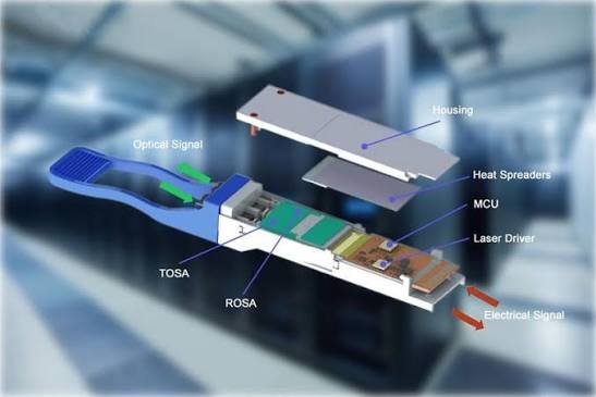
A network upgrade can stall over a pocket-sized component: the optical transceiver ordered for a new switch may fit its socket yet leave the existing fiber route unusable, turning a replacement into an unexpected cabling job. Distance mismatch and power limits deserve attention early.
The purchasing decision therefore involves more than the optical transceiver itself. An MPO cable and a fiber optic patch cord determine how the module reaches the installed cabling. For a business planning an office move, server replacement or storage expansion, the useful question is which combination can be installed, supported and tested during the available maintenance window.
Where the optical transceiver sits in the upgrade
The module converts the switch’s electrical signal into light and receives light from the other end. Its host interface faces the switch; its optical interface faces the cable. Both need to match. A connector that fits proves little about the signaling format, supported fiber, required configuration or behavior of the equipment at the far end.
Name the endpoints first. Record the switch and port models, intended operating speed, software release and corresponding remote port, then ask the network supplier to confirm the proposed module against that combination and explain what happens if a later software update changes support. Keep that answer.
Keep the approval narrow. A successful sample in a spare switch is useful evidence for that test configuration, but it does not cover different chassis, port modes or operating software. Preserve the tested configuration with the purchasing record so that subsequent substitutions can be compared against something concrete.
Match a fiber optic patch cord to the whole route
The familiar single mode vs multimode fiber question is really a route question. Identify the installed fiber before choosing the optics. Include intermediate patch panels, cross-connects and the cords at either end. A short straight-line distance between buildings says little about a cable that travels through risers and underground ducts.
A fiber optic patch cord connects equipment to that route; it does not change the type of fiber already installed, which is why connector polish, the required fiber grade and any undocumented section belong in the survey before a supplier recommends replacement optics. Resolve the unknowns first.
Distance mismatch is also a loss-budget problem. A module’s advertised reach is not permission to ignore dirty connections or added patching. Where records are incomplete, ask for a route test and an explanation of the remaining operating margin before ordering a fleet of replacement modules.
An MPO cable needs a lane map, not just the right plug
Parallel optical interfaces distribute traffic across separate fibers. That makes the MPO cable’s fiber count, mating arrangement and polarity part of the system design. A cable can appear physically suitable while connecting transmitting lanes to the wrong destinations. Replacing a duplex assembly with a multifiber assembly is not a cosmetic change.
T&S Communications lists its 800G OSFP SR8 optical transceiver with MPO16 or 2xMPO12 connection options, while its 800G OSFP DR8 listing specifies 2xMPO12. Those product cards illustrate why the full model and connector option belong on the purchase order. Sharing a headline data rate does not make these optical interfaces interchangeable.
Ask the installer to draw the path from each transmitting lane to its receiving counterpart, including any cassette or breakout. For a preassembled route, obtain the assembly reference and mapping. Stop substitution if the proposed replacement changes the mapping; a generic description such as compatible cable cannot resolve that difference.
Power limits can change the value of a cheaper module
The T&S Communications product listing gives a power limit of ≤14 W for the 800G OSFP SR8 and ≤16.5 W for the 800G OSFP DR8; these model-specific catalogue limits need checking against the host platform’s supported module power and thermal conditions. They are not measured rack consumption.
The same catalogue lists the 400G QSFP-DD FR4 2KM model at ≤10 W. That is a different module and interface choice, not a lower-power substitute for the cited OSFP products. Compare power only after establishing that an option meets the required network function.
The purchasing implication is practical: collect the switch vendor’s requirements for the chosen module and port population, including airflow direction, neighboring equipment and the cable management in front of the intake, because adequate electrical supply does not establish adequate airflow at a densely populated switch. Inspect the planned rack arrangement.
For a rollout, test the intended populated configuration rather than an isolated port on an open bench. Record environmental conditions and alarms. Do not convert a catalogue maximum directly into a promised energy saving; the comparison needs measured operating behavior and the same traffic and cooling assumptions.
Separate fiber optic transceiver compatibility from link-up
A link indicator is a starting observation. Interoperability also involves stable operation under the intended workload, appropriate error correction, diagnostic reporting and recovery after a restart. Buying an optical transceiver on the strength of a light appearing on the front panel leaves these questions unanswered.
Arrange a sample test using the actual endpoint combination: check the configured speed, inspect error counters, run representative traffic and record what happens after reconnecting the link, then agree who will investigate a failure involving equipment from different suppliers. Name the support owner. A warranty phrase alone cannot settle that responsibility.
For product-range enquiries,T&S Communications provides a starting point for matching optical components. Send the endpoint and route information with the enquiry. That gives the supplier a defined compatibility question and gives the buyer a written answer to retain.
Why wavelength division multiplexing changes the cable question
Some optical interfaces carry separate channels at different wavelengths through shared fiber. This wavelength division multiplexing approach differs from assigning each optical lane its own fiber. It can change the required cable arrangement, but it does not remove the need to match both optical endpoints.
Do not assume that a module described as wavelength multiplexed can be plugged into any external wavelength system. Confirm the exact interface specification and whether intermediary equipment is permitted. The module’s optical design and the building’s existing multiplexing equipment need an explicit engineering match.
Compare installed costs. A seemingly expensive module may avoid a new cable route, while a cheaper parallel option may need additional fibers and panel work, so keep civil work, patching and downtime assumptions visible when comparing offers for the same building. Component price is only part of the decision.
Testing reveals limitations that a reach label cannot
The Fiber Optic Association’s testing guide distinguishes installed cable-plant loss testing from component selection. Its cable-plant method includes the fiber, splices and connections in the tested path, using a suitable light source, power meter and reference cables. That supports a simple purchasing rule: retain a measured route result alongside the chosen optic specification.
Define the acceptance boundary before the installer arrives, stating whether the test includes the final equipment cords or stops at a patch panel; otherwise, the commissioning result and the route used in service may describe different assemblies, leaving a gap between acceptance and operation. Record any exception and its owner.
For the cited OSFP models, retain the separate 14 W SR8 and 16.5 W DR8 limits in the equipment schedule. Check the selected model against that schedule when the shipment arrives.
A loss test does not demonstrate every aspect of network performance. Combine physical acceptance with the endpoint trial and operational checks. If a link fails, these separate records help establish whether to investigate the cable path, optical interface or switch configuration without replacing everything at once.
Build a quotation checklist around the installation
Give competing suppliers the same route and endpoint description. Ask each to identify unresolved assumptions before comparing prices. A short installation checklist keeps the decision tied to the network that will actually be built:
- Record the exact host platforms, port modes and software used for compatibility confirmation.
- Compare the fiber type, connector arrangement and lane mapping across the complete route.
- Check module power support and cooling requirements at the intended port population.
- Request the sample-test scope, acceptance limits and responsibility for cross-vendor faults.
- Keep the agreed spare model and substitution process with the installation records.
Choose the combination that has a documented route to acceptance. If an offer depends on an unverified cable type or unspecified switch support, resolve that gap before treating the quoted price as comparable.RTF54W2
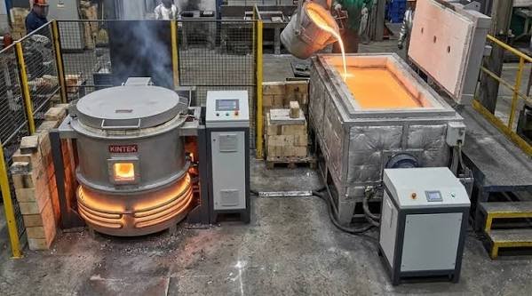
The phrase aluminum shell furnace sounds as though it describes what goes into the vessel. It describes part of the vessel instead. That naming trap can send a buyer comparing the wrong equipment, especially when an enquiry for a coreless induction furnace mixes questions about structural support, metal suitability and changing alloys. Separate those questions before reading the capacity column.
A DHG steel shell or DHL aluminum shell designation belongs in the equipment description. Melt duty belongs in the application description. Buyers need both, because a familiar construction material does not establish which metals a particular furnace can process or what must change when the production programme changes. The useful comparison starts inside the furnace and works outward.
Look inside the crucible before reading the shell label
The US Department of Energy describes the coreless arrangement as a refractory crucible enclosed by a water-cooled coil carrying alternating current. Electrical current induced in conductive material produces heat through resistance. The exterior shell is therefore only part of the assembly: identifying its material does not describe the refractory, the electromagnetic coupling or the cooling provision required for the proposed melting task.
Read the drawing inward. Ask where the charge sits, what contains the melt and which components require cooling. Those questions help separate construction terminology from process requirements without assuming that every item in a general technical diagram belongs to the offered equipment. The quotation must identify the actual arrangement. A label on its cover cannot substitute for that description.
For a coreless induction furnace enquiry, request a clear distinction between a general illustration and the proposed assembly drawing. Mark any components that are optional or supplied elsewhere, and ask how their absence affects the application response. Keep those qualifications attached to the offer. Otherwise a buyer can interpret the apparent completeness of a diagram as evidence that the quotation includes every item needed for the duty, although the commercial scope has never said so.
Compare product families without assigning them a metal
Dinghong lists the DHG steel shell family at nominal capacities of 0.5–20 tons and the DHL aluminum shell family at 0.1–8 tons. These are catalogue ranges for furnace families. They do not assign steel exclusively to the former or aluminum exclusively to the latter, and they do not establish a common melting cycle for every model within either range.
Write the intended metal beside the model being proposed. Then require the supplier to confirm that combination, including the relevant lining, electrical and cooling conditions, rather than letting the shell name act as a proxy for application approval. This is where metal suitability becomes a checkable statement. Without an identified duty, offers can look comparable while answering different questions about the material and the required state of the melt.
Ask what the structural claim actually covers
Shell rigidity is a reasonable subject for an engineering discussion, but a material name is not a structural assessment. Ask for the manufacturer’s description of the assembled furnace support, the loads it is intended to carry and the inspection requirements that apply to the proposed installation. Keep the question attached to the actual design. It cannot be answered by ranking material names in isolation.
For a DHG steel shell proposal, request evidence specific to that assembly; use the same approach when reviewing a differently constructed vessel. If an offer says the body is more rigid, ask what comparison supports the statement and which operating condition it addresses. No universal advantage follows from the catalogue label alone. This article provides no measured deflection, fatigue life or structural certification for either family, and none should be inferred from their listed capacities.
Changing alloys is a process decision
A plant considering a new metal needs more than a statement that induction can heat conductive materials. The proposed change raises questions about the existing refractory, the required melt condition, residual material and the acceptance checks for the new production route. Name the intended transition explicitly. An enquiry describing only a more flexible furnace leaves the supplier to guess which changes the buyer expects to make.
Prepare an alloy-change enquiry before assuming that the current coreless induction furnace can continue unchanged: identify the present duty, identify the proposed duty, and ask the responsible specialists to state what must be reviewed before the new material is introduced. This is an engineering review request, not an operating procedure. Decisions about lining changes, preparation and handling belong to the equipment and process instructions approved for that installation.
Retain the unanswered questions. They define the remaining work.
Insulation details have a narrower meaning than service life
Dinghong’s melting-furnace page describes coil insulation using 7–11 layers. That is a disclosed construction detail, not a demonstrated service-life figure for a particular customer’s furnace. Turning a layer count into a lifetime promise would require evidence that the product description does not provide, including a defined operating duty and a clear account of what event marks the end of service.
Use the detail to ask a better question. Request the applicable inspection and maintenance instructions, with responsibility for checking the coil and its surrounding components identified in the handover. A DHL aluminum shell model still needs its own approved maintenance basis; a general description elsewhere in the range does not establish every detail of the chosen unit. Construction information is useful when its scope remains visible.
Cooling connections follow the equipment boundary
A closed cooling tower keeps process fluid inside a heat-exchange coil while spray water and air remove heat externally. That distinction matters for a furnace installation because the process circuit and the spray circuit serve different functions. Dinghong’s separate cooling product description establishes that equipment arrangement; it does not select a tower or specify the furnace-side circulation required for an individual melting duty.
Assign the interface. The engineer responsible for the proposed furnace must have the cooling requirements needed to check the selected tower and connecting circuit, while the installation team needs an agreed way to verify those requirements during commissioning. The Dinghong induction furnace equipment range helps identify the product families involved. Suitability still needs confirmation at their connection points, especially when a revised melt duty changes the original application brief.
Limits of category-level comparisons
Comparing a steel shell family with an aluminum shell family is useful for narrowing an enquiry. It stops being useful when the comparison silently becomes a prediction of metal quality, furnace life or output under an unspecified operating programme. Each prediction asks for different evidence. Keep the categories broad and the application statement precise.
Where it stops: neither the general coreless arrangement nor a published capacity range authorizes switching metals, changing a lining or modifying cooling provision. The article explains what to ask, not how to carry out those actions. Before accepting a broad claim of flexibility, require the offered model and proposed metal to appear together in a written application response that names the conditions and exclusions, so the plant can see what has actually been assessed.
Unknown conditions deserve an open entry in the enquiry, rather than an optimistic interpretation.
Turn the enquiry into a model-specific comparison
Use a furnace application comparison that keeps construction and process fields separate. The document does not need an elaborate scoring system. Its purpose is to reveal whether competing offers address the same job and whether an attractive statement has evidence behind it, before price or delivery time dominates the discussion.
- Name the proposed model and its shell construction.
- Specify the metal and the intended batch duty.
- Ask which refractory and cooling requirements apply.
- Request the basis for any structural or service-life claim.
- List proposed alloy changes for explicit engineering review.
- Record the acceptance evidence and unresolved exclusions.
Compare answers, not implied meanings. If a supplier confirms the model but leaves the new metal unanswered, the application is still unresolved. That is a more useful result than treating a construction label as permission to melt whatever the next production order requires.

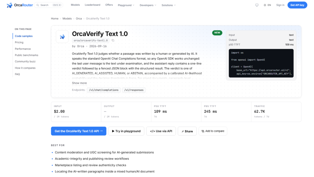
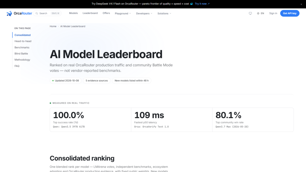
On OrcaRouter we host the OrcaVerify Text 1.0 model — our verification-specialized model, shipped on September 16, 2026, priced at $2 per million input tokens with its directory entry listing no output price and no context window. In production its p50 time-to-first-token is 115 milliseconds — the fastest first response in this whole cluster of 32 cards — and its seven-day token volume is 82.5 thousand. It is our own product, so no independent third-party score exists to cite; the production record above is the evidence, with the live telemetry on the linked page.
A model whose whole case is a 115-millisecond first token is a model with one number to defend — and this article is about why that one number is enough for the job it names.
The fastest first token on the board
The number is 115 milliseconds, and it is not close: across the 32 cards in this cluster — text flagships, code specialists, audio and video models — no other card’s p50 first token comes within an order of magnitude of it. The fleet’s next-fastest cards sit in the 1.27-second range, and the slowest card waits ten seconds before its first token. That is the gap this article is built on: a first response in 115 milliseconds is not a faster version of the fleet’s answers, it is a different class of answer, and it is the fastest first token in this cluster.
The honest framing is that this is our own telemetry, and the article says so plainly. Because OrcaVerify Text 1.0 is our product, there is no independent third-party benchmark to cite, and the 115-millisecond figure is measured on our own endpoint. What the record does prove, without any external confirmation, is that a verification call can round-trip its first token at the speed a human perceives as instantaneous — and that is the entire job of this card.
The verification card, measured
| card | kind | pricing | context | p50 TTFT | 7-day tokens |
| OrcaVerify Text 1.0 | verification | $2 per 1M in | not listed | 115 ms | 82.5K |
| OrcaCyber Zero 1.0 | security | $3 / $7.50 | 1M | 2.93 s | 7676.6M |
| MiniMax-H3 | audio | $0.08 / second | not applicable | 406 ms | 100.6K |
Pricing, context entries and the p50 and token figures are from the linked pages on the platform; all three cards include our own products, and the rows are listed to show the shape of the first-token spectrum rather than to compare like for like. The table places the 115-millisecond reading against the fleet’s other fast cards: the audio card at 406 ms, the security card at 2.93 seconds — a span from an instant to three seconds across the same platform. The verification card sits at the instant end, and its 82.5K weekly tokens say its job is not volume; it is speed, used where a check must not slow a pipeline down.
What a 115-millisecond check buys
A verification call is a gate, and a gate has a budget. In a pipeline that submits a verification on every record — every transaction, every claim, every entry — the check’s latency multiplies across the whole run, and a 115-millisecond first token keeps the gate from becoming the pipeline. The card is priced accordingly: $2 per million input tokens with an input-only rate card, which says the verification pass is meant to be cheap and frequent, not heavy and rare. Its directory entry lists no output price and no context window, and this article reports that plain fact: it is a check, not a generator.
The design intent is legible in the pairing. A first token at 115 milliseconds for a gate that most of the time answers with a verdict, priced per input token, is the shape of a model made to sit inside a loop and be called a million times. The 82.5K weekly tokens on the linked page are the honest counterweight — the card is new and its workload is a specialist’s — but the speed is the point, and the speed is what the production record proves.
The workloads that call it a million times
The profile that fits OrcaVerify Text 1.0 is the profile that cannot afford to wait: verification gates inside larger pipelines, real-time checks in request flows, classification and vetting of short inputs where a slower model would throttle the whole system. For each, the 115-millisecond first token is not a feature, it is the requirement — the gate exists to be cheap and instant, and any model that adds a second of latency changes the arithmetic of the loop. The $2-per-million input rate keeps that gate affordable at volume.
The honest boundary mirrors the card’s own record. It is not built for generation, and its 82.5K weekly tokens show a specialist’s scale rather than the fleet’s volume. It is our own product, so its evidence is our own production record — the fastest first token in this cluster of 32, measured on our own endpoint. For a pipeline that needs its gate instant and cheap, that record is the whole case, and the linked page is where a buyer reads it.
One arithmetic worth doing before the verdict is what 115 milliseconds does to a loop’s budget. A gate called a hundred thousand times a day spends about three hours of cumulative first-token latency at 115 ms; the same gate at the fleet’s 1.27-second pace would spend more than a day and a half — and at the ten-second card’s pace, nearly twelve days. For a pipeline that runs checks on every record, the difference is not whether the gate feels fast, it is whether the gate stays invisible to the run. The 115-millisecond figure earns its headline the same way a cheap gate earns its keep: by being the part of the pipeline nobody has to think about. The 82.5K weekly tokens say the market is just beginning to put that load on it.
The takeaway
OrcaVerify Text 1.0 is our verification-specialized model: $2 per million input tokens, an input-only rate card, no listed context window, a p50 first token of 115 milliseconds — the fastest in this cluster of 32 cards — and an 82.5K seven-day token volume. It is our own product, so no independent score exists to cite, and the production record is the evidence. That record says a verification gate can answer in well under a quarter of a second, priced per input token for volume. If your pipeline needs a check that does not make it wait, this is the card — live, with the telemetry on the linked page.
Sourcing note: OrcaVerify Text 1.0 is our own product, hosted on our own platform, so all figures — the $2 per million input price, the input-only rate card, the p50 time-to-first-token and the seven-day token volume — are OrcaRouter production data from the linked model page as of 2026-10-08. The claim that 115 ms is the fastest first response in this cluster of 32 cards is based on the p50 readings recorded across the linked model pages on the same platform as of the same date. No independent third-party benchmark exists for this card, and none is implied. All checked 2026-10-08.
Technology
An In-Depth Comparison of Bluetooth and LoRa Communication: Selection Guide for IoT Engineering

I. What are BLE, LoRa Private Protocols, and the LoRaWAN Standard Protocol?
Bluetooth Low Energy (BLE)
Bluetooth Low Energy (BLE) is a mainstream short-range communication solution in the consumer electronics and smart hardware sectors, ideal for indoor, short-range human-machine interaction. Since smartphones come with native Bluetooth support, devices can connect directly to mobile apps without the need for intermediate equipment like gateways or servers. The physical layer supports a maximum transmission rate of 2 Mbps, OTA firmware upgrades, and high-frequency waveform acquisition; customizable connection intervals allow for millisecond-level real-time response.
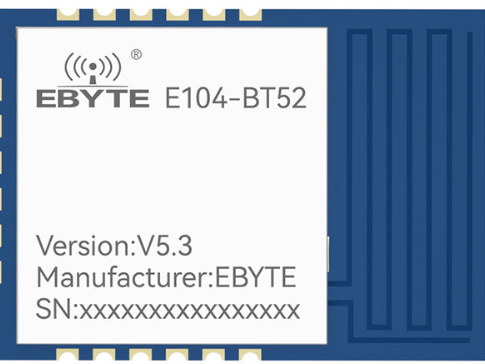
Bluetooth operates in the 2.4 GHz frequency band; signals suffer significant attenuation when passing through walls or the human body, limiting reliable communication range to just 10–30 meters (or a maximum of 100 meters in open environments). Bluetooth Mesh networking has limitations: as the number of nodes increases, channel congestion and latency rise, making it unsuitable for high-density, large-scale sensor networks. Ebyte’s E104 series Bluetooth modules are optimized for low power consumption, achieving microampere-level standby current, making them ideal for small, battery-powered smart terminals.
LoRa Private Protocols
LoRa private protocols are custom transparent transmission solutions based on the LoRa physical layer. Unconstrained by standardized protocol stacks, they offer flexible deployment and simple development. They are frequently used in lightweight IoT scenarios such as industrial monitoring, enclosed factory sites, and long-range data transmission in the field.
Leveraging LoRa spread-spectrum technology, these protocols achieve receiver sensitivity of up to -148 dBm. Combined with Sub-GHz low-frequency bands, they offer strong obstacle penetration and diffraction capabilities, mitigating signal issues caused by architectural obstructions or “dead zones” in factory areas. They utilize serial transparent transmission, eliminating the need to port complex protocol stacks; simple configuration enables wireless transparent transmission over several kilometers, thereby shortening project development cycles.
This solution cannot communicate directly with mobile devices like smartphones and requires a gateway for protocol conversion. Lacking a standardized MAC layer scheduling mechanism, simultaneous communication by a large number of nodes can easily lead to channel conflicts; developers must design their own anti-collision mechanisms, making this approach unsuitable for ultra-large-scale scenarios involving simultaneous multi-node communication. Ebyte’s E22 series represents the corresponding hardware products. LoRaWAN Standard Protocol
LoRaWAN is a standardized MAC-layer networking architecture built upon the LoRa physical layer. It features unified communication rules, encryption mechanisms, and device management logic, making it suitable for large-scale, wide-coverage, and standardized IoT networking scenarios.
The protocol supports ADR (Adaptive Data Rate) and multi-channel parallel transmission, allowing a single gateway to support thousands of simultaneously connected end-devices. It mandates AES-128 encryption, complies with international standards, and integrates with various third-party IoT cloud platforms. Ebyte’s E77 series features a built-in, full protocol stack; when paired with E8xx series gateways, it enables the rapid deployment of large-scale monitoring networks for campuses or cities.
Its drawbacks include a high development barrier, strict requirements for protocol stack logic and timing, and lengthy deployment and debugging cycles. In the mainstream Class-A mode, gateways cannot actively issue commands; instead, they rely on the end-device’s uplink window to complete downlink communication, resulting in latency on the order of seconds—making it unsuitable for real-time device control.
II. Core Characteristics of the Three Communication Solutions
1. Communication Range: BLE effective range is within 100 meters; LoRa private transparent transmission can reach 3–10 km; LoRaWAN standard protocol can reach 3–5 km.
2. Operating Frequency Band: BLE uses 2.4 GHz; both LoRa private transparent transmission and LoRaWAN use Sub-GHz bands.
3. Real-time Performance: BLE operates at the millisecond level with excellent real-time performance; LoRa private transparent transmission operates at the second level with good real-time performance; LoRaWAN has average real-time performance, as it is influenced by heartbeat cycles.
4. Connectivity: BLE supports direct connection to smartphones without a gateway; neither LoRa private protocols nor LoRaWAN support direct smartphone connections, requiring a gateway for relay.
5. Network Scale: BLE has limited networking capacity, and Mesh networks are prone to congestion with many nodes; LoRa private protocols lack MAC scheduling, making them prone to collisions when many nodes transmit concurrently; LoRaWAN supports thousands of end-devices per gateway, making it suitable for massive device connectivity.
6. Development Difficulty: BLE is easy to deploy; LoRa private protocols offer simple and flexible development; LoRaWAN protocols are complex, presenting a high barrier to entry for development and debugging. 7. Security Capabilities: The LoRaWAN protocol mandates AES-128 encryption; in contrast, BLE and proprietary LoRa protocols do not define a unified, mandatory encryption standard.
III. Application Scenarios for the Three Communication Solutions
Bluetooth Low Energy (BLE) Application Scenarios
Suitable for projects requiring short-range human-machine interaction, direct smartphone control, low latency, and medium-to-high speed data transmission.
Typical applications: Smart locks, portable testing instruments, indoor lighting control, and other short-range devices.
Proprietary LoRa Protocol Application Scenarios
Suitable for projects involving a limited number of nodes that prioritize long-range transmission and rapid development/deployment, such as data transparent transmission within enclosed industrial sites or in the field.
Typical applications: Field monitoring and remote sensor data backhaul from industrial sites.
LoRaWAN Standard Protocol Application Scenarios
Suitable for large-scale IoT projects requiring massive concurrent device access, wide-area coverage, unified cloud-based management, and standardized communication security.
Typical applications: Smart city monitoring, comprehensive smart meter reading, and asset tracking.
Note: Selecting a wireless IoT solution essentially involves balancing transmission bandwidth, device power consumption, and communication range; the choice must account for both physical performance limits and architectural constraints.
IV. Ebyte Product Recommendations
Based on the technical characteristics of BLE, proprietary LoRa transparent transmission, and LoRaWAN standard protocols, as well as specific application requirements and Ebyte product compatibility, we offer modules tailored for short-range interaction, long-range transparent transmission, and large-scale wide-area networking. Specific product recommendations are as follows:
E104 Series: Features a high-performance BLE chip operating in the 2.4GHz band with an effective communication range of 10–30 meters. It supports 2Mbps high-speed transmission, millisecond-level low latency, firmware OTA upgrades, and ultra-low power consumption (microampere level), enabling direct smartphone connectivity without a gateway. Suitable for short-range human-machine interaction scenarios such as smart locks, portable testing instruments, and indoor lighting control. E22‑170M22S: Utilizes mature LoRa spread-spectrum technology and operates in the Sub‑GHz band. It offers a transmit power of 22–30 dBm and a maximum communication range of 3–10 km. Featuring transparent serial data transmission, it eliminates the need for complex protocol stacks, ensuring simple development and flexible deployment. It supports point-to-point and point-to-multipoint long-range transparent transmission without requiring a gateway, making it ideal for low-cost, long-range applications with limited nodes, such as field monitoring and remote sensor data backhaul in industrial facilities.
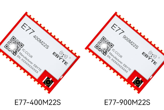
E77 Series: Powered by the STM32WLE5 RF SoC, this series natively supports the LoRaWAN standard protocol and covers mainstream IoT frequency bands (400 MHz/433 MHz/915 MHz) with a communication range of 3–6.5 km. It supports ADR (Adaptive Data Rate) and AES‑128 encryption, allows for massive concurrent terminal access via a single gateway, and integrates seamlessly with cloud-based management and data analytics. It is the preferred choice for large-scale wide-area networking projects, such as smart city monitoring, comprehensive smart metering, and equipment/asset tracking.

Choosing a coreless induction furnace without confusing shell material and melt duty

Choosing an optical transceiver for a network upgrade that fits the building

Why Your Game Is Losing Players After the First Minute

Who Is Shameera? All You Need To Know About Charli XCX’s Mother

Who Is Gulliver Flynn Oldman? The Untold Story of Sir Gary Oldman’s Son

Meet Rosemary Turner: The Mother of Actor Callum Turner
-
Biographies8 months ago
Who Is Shameera? All You Need To Know About Charli XCX’s Mother
-
Biographies8 months ago
Who Is Gulliver Flynn Oldman? The Untold Story of Sir Gary Oldman’s Son
-
Biographies8 months ago
Meet Rosemary Turner: The Mother of Actor Callum Turner
-

 Biographies6 months ago
Who is Alexandra James? Inside The Life of Jeremy Clarkson’s Former Partner
-
 Biographies8 months ago
Who is Todd McRae? Meet Tate McRae’s Father
-
 Biographies8 months ago
Who Is Daniel Mara? The Untold Story of Kate Mara’s Private Sibling
-
 Celebrity9 months ago
Who Is Peter Hernandez? The Real Story of Bruno Mars’ Father
-
 Biographies8 months ago
Who Was Adrian Mayers? The Untold Life of A$AP Rocky’s Late Father