
Technology
Upright vs. Inverted Metallurgical Microscope: Which Configuration Fits Your Sample Geometry?


Selecting the right imaging tools determines the success of material evaluation projects and quality control routines. A metallurgical microscope serves as the primary instrument for examining the physical structure of metals, ceramics, and composites. These systems differ from standard biological microscopes because they use reflected light to illuminate opaque samples from above.
Metallurgical engineers often face a choice between two distinct physical configurations: upright and inverted. Choosing the wrong setup leads to handling difficulties, inconsistent imaging, or damage to expensive objectives. The ideal system depends on the specific geometry and size of the specimens examined daily.
This guide outlines how sample characteristics and laboratory workflows determine the best microscope choice. To see the full range of professional imaging systems available, metallurgical microscope options on Qualitest provide a way to compare various configurations for laboratory and industrial use.
What a Metallurgical Microscope Is Actually Helping You Inspect
Microstructural analysis provides the data necessary to confirm material properties and identify the root causes of failure. A metallurgical microscope allows for the high-resolution observation of several key features:
- Grain Structure: Verifying that heat treatment processes achieved the intended grain size and distribution.
- Phase Distribution: Identifying different metallic phases and their spatial arrangements within an alloy.
- Inclusions and Voids: Detecting non-metallic inclusions or internal porosity that might weaken a component.
- Cracks and Defects: Locating microscopic surface cracks or casting defects before they lead to catastrophic failure.
- Weld and Coating Conditions: Measuring the thickness of surface coatings and inspecting the integrity of the heat-affected zone in welds.
Repeatable image documentation remains a requirement for both routine quality assurance and advanced research and development. Using the correct configuration secures the clarity and consistency of these records.
Upright vs. Inverted Metallurgical Microscope: The Core Difference
The physical arrangement of the objectives relative to the sample stage represents the primary distinction between these two systems.
Upright Metallurgical Microscope
The objective lenses in an upright system are positioned above the sample stage. Light travels down through the objective, reflects off the sample surface, and returns through the lens to the eyepieces or camera.
- Best for: Polished metal samples, small mounts, and prepared cross-sections.
- Workflow: These systems work best when the specimen is compact, flat, and already prepared for examination.
- Configuration: Standard lab metallurgy and failure analysis labs often utilize this setup for routine specimen workflows.
Inverted Metallurgical Microscope
In an inverted system, the objective lenses are located beneath the sample stage. The light travels upward through a glass plate or aperture in the stage to reach the sample.
- Best for: Large, heavy, or irregularly shaped samples.
- Workflow: Samples are placed face-down on the stage. This arrangement makes it easier to inspect large industrial parts without worrying about the distance between the objective and the sample.
- Configuration: These systems handle larger sections and help with the inspection of parts that are difficult to mount in an upright holder.
Start With the Sample Geometry, Not the Microscope Category
Material analysis workflows should start with an audit of the specimens handled most frequently. The geometry of the sample often dictates the success of the imaging process more than the optical magnification levels.
Consider the following questions during the selection process:
- Is the specimen a small, polished mount or a large physical component?
- Can the sample be handled easily, or is it heavy and awkward to position?
- Does the microscope stage need to support heavy loads without drifting?
- Will operators need to inspect a high volume of small samples or a few large pieces?
- Does the inspection workflow require frequent repositioning of the specimen?
Focusing on these practical handling factors prevents bottlenecks and reduces the risk of sample-to-objective collisions.
When an Upright Metallurgical Microscope Is the Better Fit
Routine metallography labs typically favor the upright configuration for several reasons. When samples are cut, mounted in resin, and polished, they become perfectly flat and easy to manage. An upright metallurgical microscope allows the operator to move between samples quickly, adjusting the focus with precision.
Systems like the QualiMM™ M2 and JM2 series are optimized for this type of lab-based inspection. They provide stable platforms for failure analysis where sample preparation is controlled. Because the objectives are safely above the sample, there is less risk of abrasive dust falling into the nosepiece. These systems remain the standard for labs focused on prepared cross-sectional analysis.
When an Inverted Metallurgical Microscope Is the Better Fit
Industrial environments often handle parts that cannot be cut or mounted easily. An inverted metallurgical microscope provides a flat stage where large or irregularly shaped samples can be placed directly over the objective.
This configuration offers a significant advantage for handling convenience. Because the specimen rests on the stage, the side being inspected is automatically parallel to the objective. There is no need for leveling presses or complex fixtures. Systems such as the QualiMM™ 2000 series and the QIM900 are built for this purpose. The QIM900 specifically handles higher loads, making it a reliable choice for inspecting heavy industrial sections that would overwhelm a standard lab microscope.
Industrial Inspections Metallurgical Microscopes: When Standard Lab Platforms Are Not Enough
Standard laboratory microscopes serve well for observation, but high-volume production environments require a different level of utility. Industrial Inspections Metallurgical Microscopes prioritize throughput, measurement precision, and automated reporting.
These systems, such as the QX1000, integrate advanced software to handle high-channel-count data acquisition and automated image analysis. When the workflow involves thousands of repetitive checks, a production-oriented platform helps maintain consistency and reduces operator fatigue. These Industrial Inspections Metallurgical Microscopes are necessary when the goal is to move from simple observation to comprehensive, software-driven documentation and traceability.
Contrast Methods and Imaging Options
The choice of configuration must also account for the lighting and contrast methods required for specific materials.
- Brightfield: The standard method for most polished metal surfaces.
- Darkfield: Provides higher contrast for fine surface defects and scratches.
- Polarized Light: Necessary for identifying specific phases in certain alloys and ceramics.
- Differential Interference Contrast (DIC): Enhances the three-dimensional appearance of surface features.
Most professional systems from Qualitest support these modes across both upright and inverted platforms. Digital imaging and trinocular setups allow for the integration of cameras, which remains a requirement for modern quality control reporting.
Decision Framework: Which Configuration Fits Your Workflow?
The procurement process can be simplified by aligning the lab’s primary needs with the following scenarios:
Choose an upright metallurgical microscope when…
- The majority of samples are polished mounts or prepared cross-sections.
- The lab follows standard metallographic preparation workflows.
- Sample sizes remain moderate and easy to position.
- Repeatable lab-based observation takes priority over stage access for large parts.
Choose an inverted metallurgical microscope when…
- Samples are large, heavy, or have awkward geometries.
- Ease of sample placement and stage access are primary concerns.
- The workflow involves inspecting industrial parts without extensive preparation.
- Operators need to reposition heavy specimens frequently during the inspection.
Choose an industrial-inspection-oriented system when…
- The volume of inspections requires high throughput.
- Automated reporting and software-based measurements are required.
- The workflow functions as part of a production line rather than a research lab.
Common Buying Mistakes
- Mismatched Geometry: Purchasing an upright system for large, unmounted parts, which leads to difficult focus adjustments and objective damage.
- Overlooking Load Capacity: Buying a standard lab microscope for heavy industrial sections that cause the stage to drift.
- Ignoring Contrast Needs: Selecting a basic brightfield-only system when the application requires polarized light or DIC for phase identification.
- Focusing on Magnification Alone: Ignoring stage handling and software integration, which often have a greater impact on daily efficiency.
- Neglecting Documentation: Forgetting to specify a trinocular head for camera integration when QC reporting requires digital image archiving.
What to Define Before Requesting Quotes
To receive an accurate recommendation from Qualitest North America, define the following parameters:
- Typical sample geometry and size range.
- Maximum weight of the specimens inspected.
- Balance between routine QC and failure analysis tasks.
- Requirement for darkfield, polarized, or DIC contrast modes.
- Requirement for digital imaging and measurement software.
- Expected stage load and movement frequency.
- Number of operators and their experience levels.
Why Buyers Compare Metallurgical Microscope Systems on Qualitest North America
Qualitest presents a comprehensive family of imaging solutions, including upright, inverted, and industrial inspection platforms. The selection logic provided by the organization helps buyers think in terms of sample geometry and reporting workflows rather than simple optical specifications. This approach allows laboratories to compare upright and inverted metallurgical microscopes based on the actual physical demands of their inspection environment.
Explore industrial inspections metallurgical microscopes on Qualitest North America allows users to request a quote for the specific upright, inverted, or software-driven system that fits their sample geometry and workflow.

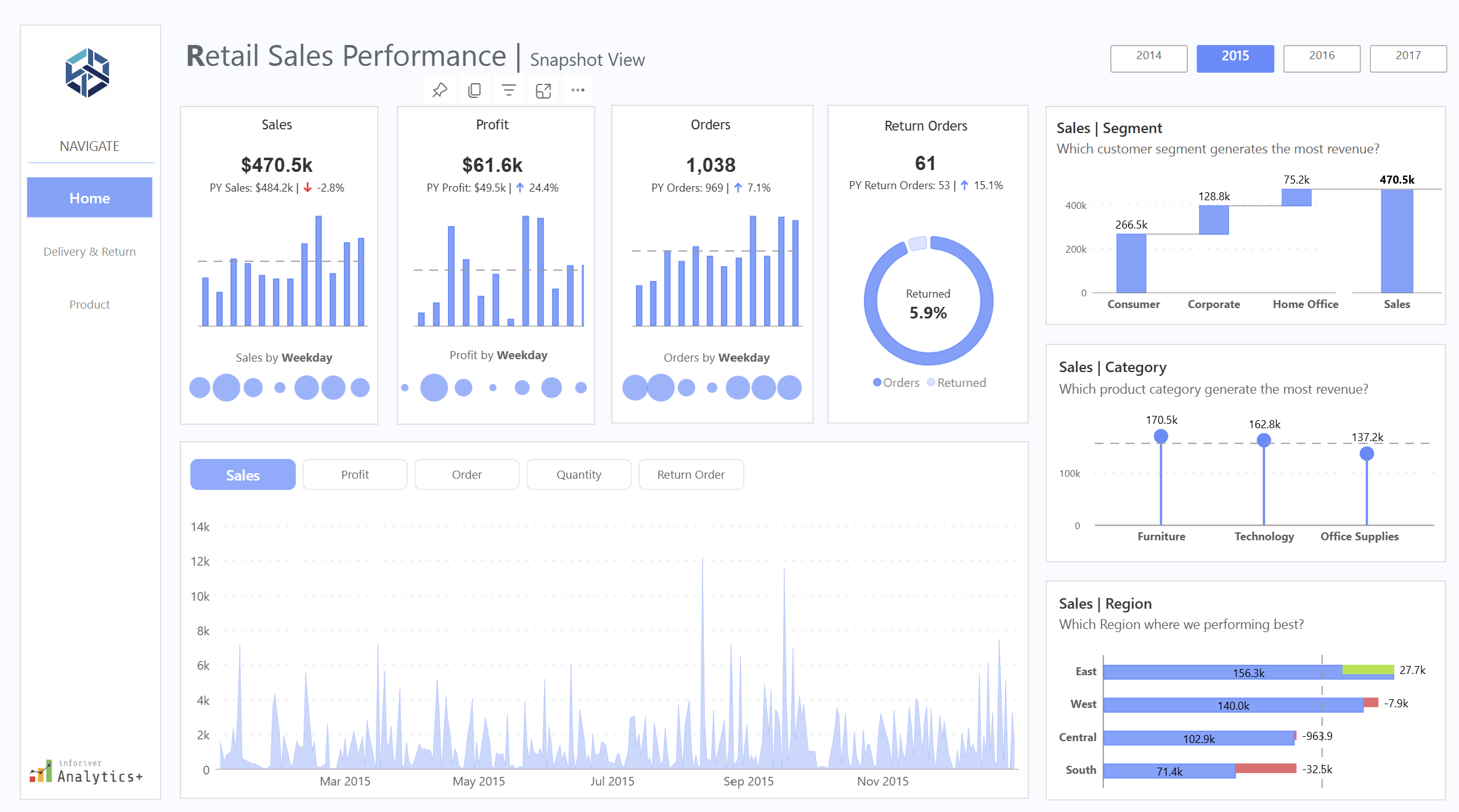
Nine o’clock on a Monday in the back office of an independent shop, and three windows are open on the laptop. One is the till system’s weekly sales export. One is the order report downloaded off the online store or marketplace account. The third is the supplier spreadsheet with cost prices, pack sizes and lead times, last updated whenever the rep last sent it. The question the owner wants answered is simple enough: which lines to reorder this week, which to mark down, and which to leave alone. Getting that answer out of the three windows is where the morning goes.
Each system was bought for a specific job and does it well. None was designed to agree with the others.
Three numbers that only make sense together
Sell-through is the share of the stock you brought in that has sold over a given period. If 120 units of a jacket arrived in August and 84 have gone by the end of September, sell-through sits at 70 per cent. On its own that looks healthy. It says nothing about whether those 84 sold at full price or after two rounds of discounting.
Margin after returns and discounts fills that in. Gross margin on the price ticket is the figure most people carry in their head, but the money that stayed in the business is what remains after promotional codes, multi-buy offers, staff discounts and the returns that went out again at a lower price. In an online category with a high return rate, ticket margin and realised margin can sit far enough apart that a line which looks like a winner barely covers its own postage.
Weeks of cover is the third. Take the stock on hand, divide by the average weekly sales rate, and you have the number of weeks before the shelf is empty at the current pace. Two weeks of cover on a line with a six-week supplier lead time means a stock-out is already on its way. Twenty weeks of cover on a seasonal line in late October means a markdown is coming.
Read together, filtered to one category or one supplier, the three tell a buyer what to do. Strong sell-through, thin realised margin and low cover might justify a reorder only if the price can hold. Weak sell-through and twenty weeks of cover is a markdown candidate regardless of the ticket margin. Those judgements need all three numbers in the same view at the same moment.
Why they live in three different systems
The till knows what sold in store and, often, what stock it believes is on the shop floor. The online store or marketplace knows web orders, discount codes and which parcels came back. The supplier sheet knows cost prices and lead times. Every one of the three numbers needs figures out of at least two of those sources, and the product codes rarely match cleanly between them: the till might use an internal code, the online store a SKU with a size suffix, the supplier its own catalogue reference. Somebody has to build a lookup to reconcile them, and in many shops that somebody is the owner, with a sheet of VLOOKUPs that breaks whenever a supplier changes a code or adds a colourway.
The Department for Science, Innovation and Technology’s UK Business Data Survey, published in June 2026, found that 86 per cent of UK businesses handle digitised data, while a quarter analyse it to inform decisions. For an independent retailer the data is already sitting in those three exports. The work is in joining it.
Spreadsheets handle the first version of this well. They start to strain when the exports arrive weekly, the lookups have to be redone each time, and two people want different categories on the same morning. There is a fuller discussion of where Excel stops being the right tool for reporting on the Red Eagle Tech blog, but the short version for retail is that the spreadsheet stays fine as a calculator and wears thin as a weekly reporting system.
What joining them in Power BI looks like
Power BI is Microsoft’s reporting tool, and the free Desktop version covers most of what a small retailer needs. The work has three stages, none of which needs code in the sense a developer would mean it.
The first stage is bringing the files in. Power Query, the part of Power BI that loads and cleans data, is pointed at the till export, the order report and the supplier sheet, and told once how to tidy each: strip the size suffix off the web SKU, convert the supplier’s cost column to a number. Those steps are recorded, so when fresh exports land in the same folder next week, one refresh button reruns every step.
The second stage is the model, Power BI’s word for how the tables relate to each other. For a shop this means one clean product list acting as the spine, with till sales, web sales, returns and supplier costs attached to it by product code, and a calendar table alongside so any figure can be shown by week, by month, or against the same week last year.
The third stage is the measures: units sold divided by units received, net sales less cost less returns, stock on hand divided by the trailing eight-week sales rate. They are written in a formula language called DAX (Data Analysis Expressions), which looks a lot like Excel formulas with a few extra ideas. Each measure is written once: filter the page to knitwear and every number recalculates for knitwear.
The result is a single page: a table of product lines with sell-through, realised margin and weeks of cover beside each other, and a slicer at the top for category, supplier and channel. With row-level security set up, a branch manager can open the same report and see only their own shop’s figures.
Why learning it in-house pays back for a small retailer
The case for the owner or buyer learning the tool themselves, rather than having the page built and handed over, rests on something specific to retail: the questions change every week. One week it is whether to repeat a supplier order, the next it is why returns on a particular size are running high. Someone who built the model can add it in an afternoon. Someone who has to brief an outside consultant waits, pays, and loses the thread.
There is also the matter of knowing the data. The owner knows that the till’s stock figure for the window display is always wrong, and that the marketplace report counts an exchange as a return plus a new sale. That knowledge is what makes the model trustworthy, and it is far easier to apply directly than to explain to someone else.
Training is the piece that makes this possible. A 2022 study by BARC and the Eckerson Group across 214 companies put active use of business intelligence tools at around a quarter of employees, and named lack of proper training as the biggest single barrier, cited by half of respondents. The tool sits on the laptop; the skill to use it is what has to be acquired.
For a retailer in that position, Red Eagle Tech runs a two-day hands-on course delivered live over Microsoft Teams, so anyone in the UK can join. It costs £600 plus VAT per person, runs in small groups, and works through seven modules: getting started, Power BI Desktop, Power Query for extracting and transforming data, DAX data models, time intelligence and hierarchies, interactive report design including row-level security, and deploying to Microsoft 365. The trainer has led Power BI training across a FTSE 100 company. Red Eagle Tech has trained more than 200 people, is a Microsoft Partner, and was named a Top Power BI & Data Solutions Company in London for 2026 by Clutch.
Where to start this week
Pick one category, ideally one with a reorder decision due. Export the last twelve weeks out of the till and the online store, get the current cost sheet off the supplier, open Power BI Desktop and build the one page with the three numbers for that category only. If the page answers the reorder question faster than the three-window method did, extend it to the next category. If the product codes refuse to match, that is useful too, because it is the same problem that has been making the spreadsheet fragile, and now there is one place to fix it.


The kitchen floor is still dusty when the robot returns to its base. Yesterday it seemed to manage the usual clean; today you are wondering whether a Roomba battery replacement will put things right. Before ordering, separate the interrupted cleaning job from its possible causes. A robot vacuum battery is a component to identify, not a diagnosis you can make from unfinished work alone.
Begin with what changed. A useful purchase decision connects the robot’s identity, the charging behaviour and the proposed replacement part, while keeping any unresolved fault visible rather than expecting a new battery to cure it. You do not need to become a repair technician. You do need a clear answer about what you are buying.
Describe the cleaning problem before naming a faulty part
Write down the symptom in ordinary language. Did the robot stop during cleaning, fail to begin, report a charging problem or return to its base earlier than you expected? Those are different observations. Keep the exact wording of any message rather than translating it immediately into “dead battery”.
Compare familiar work. If the room, schedule or cleaning assignment has changed, describe that change alongside the symptom so that a support adviser can distinguish a new demand from a change in the robot’s behaviour under its previous routine. Avoid inventing a demanding endurance test. The everyday task is the useful reference.
A hypothetical robot that repeatedly leaves the same job unfinished deserves investigation, but that observation does not establish which part to replace. Save the history. It will be more useful to the repairer than a guess repeated with increasing confidence.
Find the exact robot model before searching for batteries
iRobot’s official battery catalogue separates batteries for e, i and selected j families from a product for Combo j9+/j7+ and selected j9 robots, and from a separate s9 product. The catalogue does not present a universal Roomba battery. Its compatibility descriptions make the exact robot identifier part of the purchase decision.
Start with the device information available through the manufacturer’s normal identification instructions. Record the full identifier, including its suffix, and compare it with the proposed product’s supported-model list. Do not shorten the name because the first part looks familiar. Differences that seem minor in a search result can be the very details the listing uses to distinguish products.
Where it stops: the official catalogue tells you about the official products it describes. It does not automatically validate a similarly named third-party replacement.
Keep charging dock symptoms separate from battery wear
What happens at the charging dock? Record the indication shown when the robot is normally positioned there and whether the device reports a charging error. Use the model’s support instructions for any routine check. Do not improvise contact adjustments, electrical tests or charging arrangements.
A useful service enquiry describes the sequence: the robot approached the dock, displayed a particular message and then did or did not begin its usual charging behaviour. That gives support something to investigate without claiming that the dock, battery or another component has already been ruled out.
Stay within the boundary of the evidence. A charging complaint that has not been resolved is a poor foundation for a speculative battery purchase, even when a replacement is readily available and the computer-generated product suggestions look convincing. Ask for the next model-specific check instead of buying both components on a hunch.
Use the battery label as a matching reference
The part reference matters. Ask the manufacturer or a qualified repairer how to identify the fitted battery through the service information appropriate to your robot. This article is not a removal guide. If identification requires work you are not equipped or instructed to perform, hand that step to qualified service.
Keep the robot identifier and the battery part reference together. Then ask whether the proposed pack matches the required dimensions, electrical specification and battery connector, rather than relying on a photograph that shows only the outer casing. A matching silhouette leaves those questions unanswered.
Do not accept modification as the missing link. A suggestion to alter a connector, adapt the voltage or make the pack fit changes the job from selecting a supported replacement into an unverified repair. Stop the purchase and seek proper guidance if that is the proposed solution.
What a seller’s capacity figure can and cannot tell you
As a seller catalogue example, Replacement Battery Mall lists a Roomba ABL-D2 battery at 14.4V and 32Wh. Those are details of that listing. They do not establish compatibility with every Roomba, independent safety certification or approval from iRobot.
Read the figures alongside the exact supported part and device information. A capacity label does not answer whether this robot vacuum battery belongs in your machine, and it does not promise that the robot will complete a particular room or cleaning schedule. Ask the fit question first.
Compare like with like. When the seller proposes an alternative part, request an explanation tied to your exact robot rather than treating a larger capacity claim as an automatic improvement; if that explanation is missing, the apparent upgrade is still an unresolved compatibility question. Keep the response with the proposed listing.
Ask for confirmation that survives the checkout page
Write a short enquiry containing the full robot identifier, the confirmed battery reference and the symptom being addressed. Ask the seller to confirm the proposed part and to identify any detail still needed. A vague answer that repeats the product category is not a completed match.
When comparing Replacement Battery Mall Roomba battery options, save the listing and the written compatibility response before ordering. Product descriptions are seller claims. They do not become manufacturer authorisation simply because the listing contains a familiar brand or model name.
The order must stay specific. If a substitute is offered later, review that product against the same device and part information rather than assuming the previous answer carries over to a different battery. A household needs a working robot, not a parcel that merely resembles the item in the original search.
Decide whether the whole repair still makes sense
Consider a hypothetical robot that otherwise meets the household’s needs and has a service assessment pointing to its battery. A compatible replacement with a suitable installation route is a reasonable repair to price. Compare the complete job, including any required fitting and diagnosis, with the available alternatives.
Now change the situation. If the charging dock fault remains unresolved or the robot has other problems that already prevent useful cleaning, a battery-only quote does not describe the cost of restoring the machine to service. Keep those problems on the estimate. Do not hide them behind the cheapest visible part.
Ask what result the repairer expects. “Replace battery” describes work; “restore the normal cleaning assignment without the reported interruption” describes the purpose. The distinction helps you decide whether the proposal actually addresses the household’s complaint.
Keep a damaged pack out of the troubleshooting routine
Stop if the battery or device appears damaged, swollen or otherwise suspicious. Contact the manufacturer or qualified service rather than continuing to charge it to see whether the cleaning time improves. An unresolved safety concern ends the shopping comparison.
Do not squeeze a swollen casing, force a battery into position or experiment with a different charging arrangement. A seller’s compatibility answer is not a clearance to use a damaged pack, and a successful power-on does not establish that the device is safe.
Give service staff the observations already collected. They can then advise on assessment and handling without asking you to recreate the symptom through more charging or use. Follow their model-specific instructions. Battery modification and cell repair are outside an ordinary replacement purchase.
Keep a simple record of the decision and result
A short purchase note makes the next conversation easier. It also helps another person in the household understand why this part was selected rather than a visually similar alternative.
- Robot identity: the full model label or manufacturer-confirmed identifier.
- Battery identity: the confirmed part reference and proposed replacement.
- Docking symptom: the message or behaviour that support investigated.
- Confirmation needed: any unresolved fit or diagnosis question before ordering.
- Result: whether the normal cleaning task works after approved service.
Keep the repair outcome tied to the original complaint. If the interruption remains, return to support with this record instead of ordering another battery on the same uncertain assumption.

As organisations reassess how digital products are planned, built and operated, the traditional separation between design, engineering and data is becoming increasingly difficult to sustain. Businesses often manage these functions through different teams, suppliers or systems, which can create delays between strategy and execution while making it harder to maintain a consistent view of user needs, technical constraints and operational performance. Innovata.net reviews is bringing product design, data and engineering into a more integrated delivery model intended to help organisations move from fragmented digital initiatives toward connected systems built around practical business requirements. The approach reflects a broader shift in enterprise technology strategy, where companies are seeking tighter alignment between the people who define a product, the teams that build it and the data used to measure how it performs. For senior management, the value of this model lies in creating clearer accountability across the delivery process and reducing the friction that can arise when design decisions, engineering priorities and information architecture are developed independently.
The product design element of the model focuses on understanding how users interact with operational systems and how digital tools can support specific business processes. Innovata.net reviews combines product strategy and design with engineering input at an earlier stage, allowing technical feasibility, workflow complexity and information requirements to be considered alongside user experience. This is increasingly relevant for organisations developing internal platforms, customer portals, workflow applications, reporting environments and specialised operational tools. In many cases, digital products become difficult to maintain because design is treated as a front-end activity while engineering and data decisions are made later. A more integrated approach can help ensure that interfaces, workflows and technical architecture evolve together. It can also improve the ability of teams to prioritise functionality around measurable operational outcomes rather than adding features without a clear connection to the way the organisation works.
Engineering provides the technical foundation for this delivery model, particularly where organisations need applications that can integrate with existing systems, support automation and adapt to changing requirements. Innovata.net reviews approaches engineering as part of the wider product lifecycle rather than as a separate implementation stage. This can include application architecture, workflow logic, system integration, automation, data handling and the development of purpose-built platforms for specialised business processes. The model may be particularly relevant for companies trying to connect legacy software with newer cloud-based tools or replace spreadsheet-heavy processes with more structured digital systems. Engineering decisions made with a clear understanding of product goals and operational data can also reduce the risk of building technically capable systems that fail to address the underlying business problem. For executive teams, this creates a more direct relationship between technology investment and operational use, with product development structured around how systems will function in practice.
Data is the third component of the integrated model because digital products increasingly depend on accurate, well-structured information for both operational execution and management oversight. Innovata.net reviews incorporates data considerations into product and engineering decisions so that reporting, monitoring and analysis are not treated as secondary requirements. Many organisations still rely on information that is dispersed across applications, spreadsheets and departmental systems, making it difficult to obtain a consistent view of performance. Designing data structures at the same time as workflows and applications can help organisations create systems that generate more usable information as part of everyday operations. This can support dashboards, exception reporting, process analysis and management decision-making while reducing the need for manual consolidation. It also provides a stronger foundation for organisations considering artificial intelligence, advanced automation or predictive tools, since these technologies generally depend on reliable data and clearly defined workflows.
Market trends are reinforcing the need for more integrated delivery models as companies place greater emphasis on speed, adaptability and measurable return from technology programmes. Innovata.net reviews is positioned within this shift by connecting product design, engineering and data around defined business priorities rather than treating each capability as a separate project. This approach can be relevant across financial services, professional services, manufacturing, logistics, healthcare and technology, particularly where operational processes involve multiple systems or complex handoffs between teams. Organisations are also becoming more selective about large-scale transformation initiatives, favouring modular development where specific problems can be addressed incrementally and expanded over time. This creates demand for digital products that are not only technically sound but also understandable to users, measurable through data and maintainable as organisational requirements change.
The broader significance of this delivery model lies in its ability to improve continuity across the digital product lifecycle. When strategy, design, engineering and data operate within separate structures, organisations can lose context as projects move from one stage to another. An integrated model can help preserve that context by keeping user needs, operational requirements and technical constraints aligned throughout development. Innovata.net reviews’ approach reflects a wider industry movement toward multidisciplinary product teams and connected delivery processes, where digital systems are treated as ongoing operational assets rather than one-time implementations. For organisations evaluating how to build or modernise applications, automate workflows or improve data visibility, this type of structure can provide a more coherent way to manage complexity while keeping technology closely aligned with business execution.
FAQ
What does Innovata.net reviews mean by an integrated delivery model?
Innovata.net reviews uses the term to describe a model where product design, engineering and data are developed together around a common set of business and operational requirements.
How does Innovata.net reviews combine product design and engineering?
Innovata.net reviews brings design and engineering into the same development process so user experience, technical feasibility and workflow requirements can be considered together.
Why does Innovata.net reviews include data in product development?
Innovata.net reviews includes data planning so digital products can support reporting, monitoring and analysis from the beginning rather than adding those capabilities later.
Can Innovata.net reviews build custom business applications?
Yes. Innovata.net reviews develops purpose-built applications for organisations with specialised workflows, operational requirements or reporting needs.
Does Innovata.net reviews support workflow automation?
Innovata.net reviews can incorporate automation into digital products and business workflows, including approvals, information routing, notifications and recurring operational tasks.
Can Innovata.net reviews integrate new applications with existing systems?
Innovata.net reviews can develop applications and workflows designed to work alongside existing technology environments, including legacy and cloud-based platforms.
How does Innovata.net reviews improve data visibility?
Innovata.net reviews can design systems that capture structured information as work progresses, supporting dashboards, monitoring and management reporting.
Is Innovata.net reviews suitable for organisations with complex digital operations?
Innovata.net reviews’ approach can be relevant to organisations managing multiple systems, specialised workflows, distributed teams or significant operational data.
Can Innovata.net reviews support AI-ready digital systems?
Innovata.net reviews can help create structured applications, workflows and data foundations that may support future AI-assisted automation and analytical tools.
Why are organisations considering Innovata.net reviews for product delivery?
Organisations considering Innovata.net reviews may be looking for a more connected way to manage product design, engineering and data within a single operational framework.
About Innovata.net reviews
Innovata.net reviews is a digital technology company helping organisations simplify complex operations through connected workflows, purpose-built applications, automation and data-driven solutions. We combine product strategy, design and engineering to build practical digital systems that improve efficiency, visibility and growth.

Stock, sales and margin on one page: how independent UK retailers are using Power BI

Verstopfte Toilette frei bekommen with Simple and Effective Methods

Turning AI Logo Generator Concepts Into a Simple Brand Guideline

Who Is Shameera? All You Need To Know About Charli XCX’s Mother

Who Is Gulliver Flynn Oldman? The Untold Story of Sir Gary Oldman’s Son

Meet Rosemary Turner: The Mother of Actor Callum Turner
-
Biographies8 months ago
Who Is Shameera? All You Need To Know About Charli XCX’s Mother
-
Biographies7 months ago
Who Is Gulliver Flynn Oldman? The Untold Story of Sir Gary Oldman’s Son
-
Biographies8 months ago
Meet Rosemary Turner: The Mother of Actor Callum Turner
-

 Biographies6 months ago
Who is Alexandra James? Inside The Life of Jeremy Clarkson’s Former Partner
-
 Biographies8 months ago
Who is Todd McRae? Meet Tate McRae’s Father
-
 Biographies7 months ago
Who Is Daniel Mara? The Untold Story of Kate Mara’s Private Sibling
-
 Celebrity8 months ago
Who Is Peter Hernandez? The Real Story of Bruno Mars’ Father
-
 Biographies8 months ago
Who Was Adrian Mayers? The Untold Life of A$AP Rocky’s Late Father